Product Description
Product Description
COUPLINGS
| HRC | FCL | Chain coupling | GE | L | NM | MH | Torque limiter |
| HRC 70B | FCL90 | KC4012 | GE14 | L050 | NM50 | MH45 | TL250-2 |
| HRC 70F | FCL100 | KC4014 | GE19 | L070 | NM67 | MH55 | TL250-1 |
| HRC 70H | FCL112 | KC4016 | GE24 | L075 | NM82 | MH65 | TL350-2 |
| HRC 90B | FCL125 | KC5014 | GE28 | L090 | NM97 | MH80 | TL350-1 |
| HRC 90F | FCL140 | KC5016 | GE38 | L095 | NM112 | MH90 | TL500-2 |
| HRC 90H | FCL160 | KC6018 | GE42 | L099 | NM128 | MH115 | TL500-1 |
| HRC 110B | FCL180 | KC6571 | GE48 | L100 | NM148 | MH130 | TL700-2 |
| HRC 110F | FCL200 | KC6571 | GE55 | L110 | NM168 | MH145 | TL700-1 |
| HRC 110H | FCL224 | KC8018 | GE65 | L150 | NM194 | MH175 | |
| HRC 130B | FCL250 | KC8571 | GE75 | L190 | NM214 | MH200 | |
| HRC 130F | FCL280 | KC8571 | GE90 | L225 | |||
| HRC 130H | FCL315 | KC1571 | |||||
| HRC 150B | FCL355 | KC12018 | |||||
| HRC 150F | FCL400 | KC12571 | |||||
| HRC 150H | FCL450 | ||||||
| HRC 180B | FCL560 | ||||||
| HRC 180F | FCL630 | ||||||
| HRC 180H | |||||||
| HRC 230B | |||||||
| HRC 230F | |||||||
| HRC 230H | |||||||
| HRC 280B | |||||||
| HRC 280F | |||||||
| HRC 280H |
Catalogue
Workshop
Lots of coupling in stock
FAQ
Q1: Are you trading company or manufacturer ?
A: We are factory.
Q2: How long is your delivery time and shipment?
1.Sample Lead-times: 10-20 days.
2.Production Lead-times: 30-45 days after order confirmed.
Q3: What is your advantages?
1. The most competitive price and good quality.
2. Perfect technical engineers give you the best support.
3. OEM is available.
/* January 22, 2571 19:08:37 */!function(){function s(e,r){var a,o={};try{e&&e.split(“,”).forEach(function(e,t){e&&(a=e.match(/(.*?):(.*)$/))&&1
| Standard Or Nonstandard: | Standard |
|---|---|
| Structure: | Flexible |
| Material: | Cast Iron |
| Type Name: | FCL |
| Origin: | Zhejiang |
| Customization: |
Available
| Customized Request |
|---|
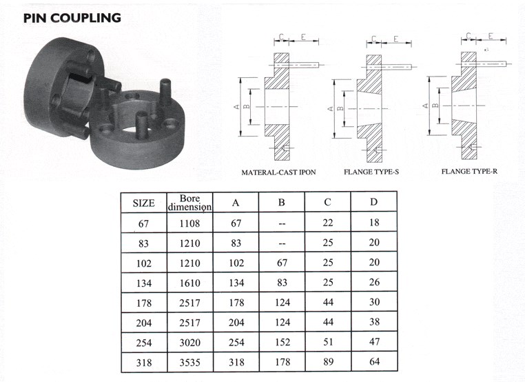
How Does a Pin Coupling Protect Connected Equipment from Shock Loads and Vibrations?
Pin couplings are designed to provide excellent protection to connected equipment from shock loads and vibrations, ensuring the smooth and reliable operation of the machinery. The unique features of pin couplings contribute to their ability to absorb and dampen shock loads and vibrations effectively:
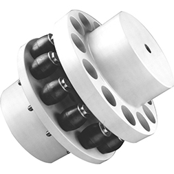
- Flexibility: Pin couplings possess a certain degree of flexibility due to the presence of movable pins. When subjected to sudden shock loads or vibrations, the pins can flex and move slightly, absorbing the impact and preventing it from transmitting directly to the connected equipment. This flexibility helps in reducing stress and minimizing the risk of damage to the machinery.
- Torsional Compliance: The pin coupling’s design allows for a certain amount of torsional compliance. This means that when the connected shafts experience slight misalignments or angular displacements, the pin coupling can compensate for these variations without causing additional stress or vibration in the system. This feature ensures that the machinery remains in proper alignment even under dynamic conditions, reducing wear and tear.
- Damping Characteristics: The presence of movable pins introduces damping characteristics to the coupling. When vibrations occur in the system, the pins can dampen these oscillations, preventing resonance and the amplification of vibrations. This damping effect improves the overall stability and performance of the machinery.
- Strength and Resilience: High-quality pin couplings are constructed from durable materials with excellent fatigue resistance. This enables the coupling to withstand repeated shock loads and vibrations over an extended period without compromising its integrity. The strength and resilience of the pin coupling contribute to the protection of the connected equipment.
Overall, pin couplings are reliable and versatile components that can effectively protect connected equipment from shock loads and vibrations. Their flexibility, torsional compliance, damping characteristics, and robust construction make them suitable for various industrial applications where shock and vibration mitigation are essential for maintaining the health and longevity of machinery and equipment.
Impact of Pin Coupling on the Overall Reliability of Connected Equipment
A pin coupling plays a crucial role in enhancing the overall reliability and performance of connected equipment in various industrial applications. Its design and construction contribute to several factors that influence reliability:
1. Torque Transmission: Pin couplings efficiently transmit torque between the driving and driven shafts, ensuring smooth power transfer without slippage or loss. This consistent torque transmission helps maintain the stability and reliability of the system during operation.
2. Misalignment Compensation: Pin couplings are designed to accommodate small amounts of angular, parallel, and axial misalignment between shafts. By tolerating misalignment, the coupling reduces stress on connected equipment, bearings, and seals, thereby enhancing reliability and extending the service life of these components.
3. Shock and Vibration Absorption: In applications with dynamic loads, such as pumps, compressors, and heavy machinery, pin couplings help dampen shock and vibrations. By absorbing and reducing these impact forces, the coupling minimizes stress on the system and prevents premature component failure.
4. Simplified Maintenance: Pin couplings generally have a simple design, making them easy to install and maintain. The ease of maintenance ensures that the coupling can be regularly inspected, lubricated, and replaced when necessary, reducing downtime and increasing the overall reliability of the equipment.
5. Corrosion Resistance: Depending on the materials used, pin couplings can be highly resistant to corrosion, making them suitable for use in harsh or corrosive environments. This corrosion resistance prevents degradation of the coupling and its components, enhancing reliability and longevity.
6. Enhanced Durability: High-quality pin couplings are manufactured from robust materials and undergo precise machining processes. These attributes contribute to the coupling’s durability, allowing it to withstand heavy loads and harsh conditions over an extended period.
7. Balanced Design: The design of a pin coupling ensures that the load is evenly distributed between the driving and driven shafts. This balanced load distribution reduces stress concentrations, minimizes wear, and increases the reliability of connected equipment.
8. Compliance with Standards: Reputable pin coupling manufacturers ensure their products comply with industry standards and regulations. Meeting these standards ensures that the coupling is designed and manufactured to specific quality criteria, enhancing reliability and safety.
Overall, a well-selected and properly installed pin coupling can significantly improve the reliability and performance of connected equipment. It helps prevent unexpected failures, reduces downtime, and contributes to the overall efficiency of industrial processes.
Can Pin Couplings Handle Misalignment Between Shafts?
Yes, pin couplings are designed to accommodate a certain degree of misalignment between shafts in rotating machinery. They are considered flexible couplings, which means they can provide some degree of angular, parallel, and axial misalignment capability.
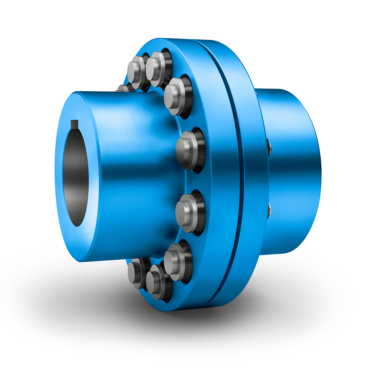
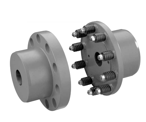
Pin couplings typically consist of two hubs, each connected to a shaft, and a central sleeve with pins that transmit torque between the hubs. The pins allow for a limited range of movement, which helps to compensate for slight misalignments between the shafts.
The angular misalignment capacity of a pin coupling is achieved through the bending of the pins. When the shafts are misaligned at an angle, the pins on one side of the coupling experience bending while those on the opposite side are in tension. The pins are designed to withstand these bending and tension forces within their elastic limits, ensuring proper functioning and longevity of the coupling.
Similarly, the pins can accommodate parallel misalignment by sliding within the pin holes of the coupling’s central sleeve. This sliding action allows the hubs to move slightly relative to each other, compensating for any offset between the shafts.
However, it is essential to note that pin couplings have limitations in terms of the amount of misalignment they can handle. Excessive misalignment beyond their specified limits can lead to increased wear on the pins and other coupling components, reducing the coupling’s effectiveness and potentially causing premature failure.
While pin couplings are suitable for applications with moderate misalignment requirements, they may not be the best choice for applications with significant misalignment or where precise alignment is critical. In such cases, more flexible couplings like gear or elastomeric couplings may be more appropriate.
Overall, when considering the use of pin couplings, it is essential to carefully evaluate the specific misalignment requirements of the application and select a coupling that can adequately accommodate those misalignments while ensuring reliable and efficient power transmission.


editor by CX 2024-04-08
China FCL Flexible Shaft Couplings for Gearbox and Motor Screw Coupling Transmission Shaft Coupling for Spinning and Weaving Machines manufacturer
Merchandise Description
FCL Adaptable Shaft Couplings for Gearbox and Motor Screw Coupling Transmission Shaft Coupling for Spinning and Weaving Equipment
Characteristics
- Compact developing, effortless set up.
- Practical maintenance, small dimension, and lightweight.
- Commonly utilized in medium and small energy transmission techniques pushed by motors, this kind of as speed reducers, hoists, compressors, conveyors, sp
Item Description
| Measurement | N.m | r/min |
D | D1 | d1 | L | C | n-M | kg | |
| FCL90 | 4 | 4000 | ninety | 35.five | eleven | 28 | three | four-M8 | one.7 | |
| FCL100 | ten | 4000 | 100 | 40 | 11 | 35.five | three | 4-M10 | 2.3 | |
| FCL112 | 16 | 4000 | 112 | 45 | 13 | forty | three | four-M10 | two.8 | |
| FCL125 | 25 | 4000 | a hundred twenty five | sixty five | fifty | thirteen | forty five | 3 | 4-M12 | 4 |
| FCL140 | fifty | 4000 | a hundred and forty | seventy one | sixty three | 13 | fifty | three | six-M12 | 5.four |
| FCL160 | 110 | 4000 | 160 | 80 | 15 | fifty six | three | 8-M12 | eight | |
| FCL180 | 157 | 3500 | 180 | 90 | 15 | sixty three | 3 | 8-M12 | 10.5 | |
| FCL200 | 245 | 3200 | 200 | 100 | 21 | 71 | 4 | eight-M20 | 16.2 | |
| FCL224 | 392 | 2850 | 224 | 112 | 21 | eighty | 4 | eight-M20 | 21.three | |
| FCL250 | 618 | 2550 | 250 | 125 | twenty five | ninety | four | 8-M24 | 31.six | |
| FCL280 | 980 | 2300 | 280 | 140 | 34 | one hundred | 4 | eight-M24 | forty four | |
| FCL315 | 1568 | 2050 | 315 | 160 | forty one | 112 | four | 10-M24 | fifty seven.7 | |
| FCL355 | 2450 | 1800 | 355 | 180 | 60 | one hundred twenty five | 5 | 8-M30 | 89.5 | |
| FCL400 | 3920 | 1600 | 400 | 200 | sixty | one hundred twenty five | 5 | ten-M30 | 113 | |
| FCL450 | 6174 | 1400 | 450 | 224 | sixty five | 140 | 5 | twelve-M30 | a hundred forty five | |
| FCL560 | 9800 | 1150 | 560 | 250 | eighty five | 160 | 5 | fourteen-M30 | 229 | |
| FCL630 | 15680 | 1000 | 630 | 280 | 95 | a hundred and eighty | five | 18-M30 | 296 | |
Relevant Products
Company Profile
FAQ
Q: How to ship to us?
A: It is offered by air, sea, or train.
Q: How to spend the funds?
A: T/T and L/C are desired, with distinct currencies, like USD, EUR, RMB, and many others.
Q: How can I know if the product is suitable for me?
A: >1ST verify drawing and specification >2nd check sample >3rd start mass production.
Q: Can I come to your firm to check out?
A: Yes, you are welcome to pay a visit to us at any time.
|
US $5 / Piece | |
1,000 Pieces (Min. Order) |
###
|
Shipping Cost:
Estimated freight per unit. |
To be negotiated |
|---|
###
| Standard Or Nonstandard: | Standard |
|---|---|
| Shaft Hole: | 11-95 |
| Torque: | >80N.M |
###
| Samples: |
US$ 5/Piece
1 Piece(Min.Order) |
|---|
###
| Customization: |
Available
|
|---|
###
| SIZE | N.m | r/min |
D | D1 | d1 | L | C | n-M | kg | |
| FCL90 | 4 | 4000 | 90 | 35.5 | 11 | 28 | 3 | 4-M8 | 1.7 | |
| FCL100 | 10 | 4000 | 100 | 40 | 11 | 35.5 | 3 | 4-M10 | 2.3 | |
| FCL112 | 16 | 4000 | 112 | 45 | 13 | 40 | 3 | 4-M10 | 2.8 | |
| FCL125 | 25 | 4000 | 125 | 65 | 50 | 13 | 45 | 3 | 4-M12 | 4 |
| FCL140 | 50 | 4000 | 140 | 71 | 63 | 13 | 50 | 3 | 6-M12 | 5.4 |
| FCL160 | 110 | 4000 | 160 | 80 | 15 | 56 | 3 | 8-M12 | 8 | |
| FCL180 | 157 | 3500 | 180 | 90 | 15 | 63 | 3 | 8-M12 | 10.5 | |
| FCL200 | 245 | 3200 | 200 | 100 | 21 | 71 | 4 | 8-M20 | 16.2 | |
| FCL224 | 392 | 2850 | 224 | 112 | 21 | 80 | 4 | 8-M20 | 21.3 | |
| FCL250 | 618 | 2550 | 250 | 125 | 25 | 90 | 4 | 8-M24 | 31.6 | |
| FCL280 | 980 | 2300 | 280 | 140 | 34 | 100 | 4 | 8-M24 | 44 | |
| FCL315 | 1568 | 2050 | 315 | 160 | 41 | 112 | 4 | 10-M24 | 57.7 | |
| FCL355 | 2450 | 1800 | 355 | 180 | 60 | 125 | 5 | 8-M30 | 89.5 | |
| FCL400 | 3920 | 1600 | 400 | 200 | 60 | 125 | 5 | 10-M30 | 113 | |
| FCL450 | 6174 | 1400 | 450 | 224 | 65 | 140 | 5 | 12-M30 | 145 | |
| FCL560 | 9800 | 1150 | 560 | 250 | 85 | 160 | 5 | 14-M30 | 229 | |
| FCL630 | 15680 | 1000 | 630 | 280 | 95 | 180 | 5 | 18-M30 | 296 | |
|
US $5 / Piece | |
1,000 Pieces (Min. Order) |
###
|
Shipping Cost:
Estimated freight per unit. |
To be negotiated |
|---|
###
| Standard Or Nonstandard: | Standard |
|---|---|
| Shaft Hole: | 11-95 |
| Torque: | >80N.M |
###
| Samples: |
US$ 5/Piece
1 Piece(Min.Order) |
|---|
###
| Customization: |
Available
|
|---|
###
| SIZE | N.m | r/min |
D | D1 | d1 | L | C | n-M | kg | |
| FCL90 | 4 | 4000 | 90 | 35.5 | 11 | 28 | 3 | 4-M8 | 1.7 | |
| FCL100 | 10 | 4000 | 100 | 40 | 11 | 35.5 | 3 | 4-M10 | 2.3 | |
| FCL112 | 16 | 4000 | 112 | 45 | 13 | 40 | 3 | 4-M10 | 2.8 | |
| FCL125 | 25 | 4000 | 125 | 65 | 50 | 13 | 45 | 3 | 4-M12 | 4 |
| FCL140 | 50 | 4000 | 140 | 71 | 63 | 13 | 50 | 3 | 6-M12 | 5.4 |
| FCL160 | 110 | 4000 | 160 | 80 | 15 | 56 | 3 | 8-M12 | 8 | |
| FCL180 | 157 | 3500 | 180 | 90 | 15 | 63 | 3 | 8-M12 | 10.5 | |
| FCL200 | 245 | 3200 | 200 | 100 | 21 | 71 | 4 | 8-M20 | 16.2 | |
| FCL224 | 392 | 2850 | 224 | 112 | 21 | 80 | 4 | 8-M20 | 21.3 | |
| FCL250 | 618 | 2550 | 250 | 125 | 25 | 90 | 4 | 8-M24 | 31.6 | |
| FCL280 | 980 | 2300 | 280 | 140 | 34 | 100 | 4 | 8-M24 | 44 | |
| FCL315 | 1568 | 2050 | 315 | 160 | 41 | 112 | 4 | 10-M24 | 57.7 | |
| FCL355 | 2450 | 1800 | 355 | 180 | 60 | 125 | 5 | 8-M30 | 89.5 | |
| FCL400 | 3920 | 1600 | 400 | 200 | 60 | 125 | 5 | 10-M30 | 113 | |
| FCL450 | 6174 | 1400 | 450 | 224 | 65 | 140 | 5 | 12-M30 | 145 | |
| FCL560 | 9800 | 1150 | 560 | 250 | 85 | 160 | 5 | 14-M30 | 229 | |
| FCL630 | 15680 | 1000 | 630 | 280 | 95 | 180 | 5 | 18-M30 | 296 | |
What Is a Coupling?
A coupling is a device that connects two shafts together. It transmits power from one to the other and is used to join rotating equipment. It can also allow for some degree of misalignment and end movement. It is used in mechanical engineering and manufacturing. To learn more about couplings, read this article. Mechanical connection between two objectsThe present invention relates to a method and assembly for forming a mechanical connection between two objects. The methods of this invention are suitable for connecting both solid and hollow objects. For example, the method can be used to make mechanical connections between two cylinders. This method is particularly useful for connecting two cylinders that are positioned near each other.
Absorbs vibration
A coupling insert is a part of a vehicle’s drivetrain that absorbs vibrations. These inserts are designed to prevent couplings from moving out of phase. However, the coupling inserts themselves can wear out and need to be replaced. Universal joints are an alternative if the coupling is out of phase by more than one degree. In addition, internal bearings in the coupling need to be lubricated and replaced when they begin to show signs of wear.
Another embodiment of the invention includes a flexible coupling 25 that includes rearwardly-extending lugs that extend toward the coupling member 23. These lugs interdigitate with corresponding lugs on the coupling member 23. They are spaced circumferentially. A first elastic member 28 is interposed between lugs 26 and 27, and is adapted to yield in a counterclockwise direction. As a result, it absorbs torsional vibrations.
Blocks heat transfer
Thermal coupling occurs when a solid block is thermally coupled to the air or fluid passing through it. The amount of heat transferred through a solid block depends on the heat transfer coefficients of the materials. This paper presents a numerical model to understand how heat transfers through different block materials. This work also describes the thermal resistance network for a one-dimensional block.
In some cases, thermal coupling increases the heat transfer mechanism. As illustrated in FIG. 1D, a heatpipe coupler 112 couples two heatpipes 110-1 and 110-2. This configuration allows the pipes to be coupled to the heat source and to the condenser. In addition, the heat pipe couplers may have bellows at the ends to help facilitate linear motion.
Thermal coupling is achieved by ensuring that at least one block is made of a material with a lower thermal expansion coefficient than the annulus. Ideally, the block’s mean thermal expansion coefficient is at least twenty percent lower than the annulus’s mean thermal expansion coefficient. This ensures that the thermal coupling between the two parts is as efficient as possible.
Another type of thermal coupling is achieved by using flexible elements. These are often washers or springs. These components allow the blocks to maintain physical contact with the post 55, which means that the heat transfer is more efficient even at higher temperatures. The flexibility of these elements also makes it possible to choose an element that will not impede assembly.
Protects rotating equipment
A reliable, long-lasting coupling system can reduce the risk of damage to rotating equipment. Designed to protect against torque overload and wear, Voith torque-limiting couplings provide outstanding safety and reliability. As a result, they can deliver maximum performance and minimize equipment downtime. In addition to their long-term benefits, these solutions are ideal for applications where safety and reliability are of paramount importance.
A good coupling provides many advantages, including the ability to transmit power, compensate for axial movement, and absorb shock. It is essential to choose the proper coupling for your application based on the basic conditions of your rotating equipment. For example, if you have two shafts with parallel rotation axes, you should choose a parallel coupling. Otherwise, you should use an angular coupling.
Torque-limiting couplings can also provide protection for rotating equipment by disengaging at a specific torque level. This protects the drive shaft from undergoing catastrophic failure. Torque limiters are particularly helpful for high-value equipment. By preventing catastrophic failure, you can avoid expensive repairs and minimize equipment downtime.
Coupling guards are easy to install and provide effective protection for rotating equipment. These covers are made of sheet metal bent to fit over the shaft. They are durable and easy to remove when necessary. This type of guard can prevent employees from catching their hands, tools, or loose clothing on motor coupling components.
editor by czh 2023-01-28