Product Description
Gear coupling flexible Fluid Flange HRC Spacer PIN MH Rigid NM Jaw Steel chain brake standard drum wheel rolling shaft steel transmission parts
Ever-Power industry is 1 of the biggest couplings manufacturer in China, have already exported lots of gear couplings, Jaw couplings, chain couplings etc.. to Japan, Korea, Italy , USA …..
/* March 10, 2571 17:59:20 */!function(){function s(e,r){var a,o={};try{e&&e.split(“,”).forEach(function(e,t){e&&(a=e.match(/(.*?):(.*)$/))&&1
| Standard Or Nonstandard: | Standard |
|---|---|
| Shaft Hole: | 8-24 |
| Torque: | >80N.M |
| Bore Diameter: | 19mm |
| Speed: | 4000r/M |
| Structure: | Flexible |
| Samples: |
US$ 9999/Piece
1 Piece(Min.Order) | |
|---|
How Do Pin Couplings Compare to Other Types of Couplings in Terms of Performance?
Pin couplings offer certain advantages and disadvantages compared to other types of couplings, and their performance characteristics can vary depending on the specific application requirements. Below is a comparison of pin couplings with some commonly used couplings:
1. Gear Couplings:
- Flexibility: Gear couplings are more rigid than pin couplings and may not offer the same level of misalignment capacity.
- Torsional Stiffness: Gear couplings provide higher torsional stiffness, making them suitable for applications requiring precise torque transmission.
- Shock Absorption: Gear couplings can handle higher shock loads due to their robust design and greater stiffness.
- Maintenance: Gear couplings may require periodic lubrication and maintenance compared to maintenance-free pin couplings.
- Applications: Gear couplings are commonly used in heavy-duty and high-torque applications where precise torque transmission is essential.
2. Flexible (Elastomeric) Couplings:
- Flexibility: Elastomeric couplings offer higher misalignment capacity than pin couplings and can handle angular, parallel, and axial misalignment.
- Shock Absorption: Elastomeric couplings provide excellent shock absorption, damping vibrations, and protecting connected equipment.
- Torsional Stiffness: Elastomeric couplings have lower torsional stiffness compared to pin couplings, making them more forgiving in high shock load applications.
- Installation: Elastomeric couplings are easy to install and require no lubrication, making them maintenance-free.
- Applications: Elastomeric couplings are commonly used in pumps, compressors, and other machinery where vibration isolation is crucial.
3. Rigid Couplings:
- Torsional Stiffness: Rigid couplings provide high torsional stiffness, ensuring accurate torque transmission.
- Misalignment Capacity: Rigid couplings have little to no misalignment capacity and require precise shaft alignment.
- Applications: Rigid couplings are used in applications where precise alignment is essential, such as shaft-to-shaft connections in high-precision systems.
Conclusion:
Pin couplings strike a balance between flexibility and torsional stiffness, making them suitable for applications with moderate misalignment and shock loads. They are often used in general industrial applications, conveyors, and light to medium-duty machinery.
When selecting a coupling for a specific application, it is crucial to consider factors such as misalignment requirements, shock and vibration loads, torsional stiffness, maintenance needs, and the level of precision required. Each coupling type has its strengths and weaknesses, and the appropriate choice will depend on the specific demands of the application.
Can Pin Couplings Be Used for Both Motor-to-Shaft and Shaft-to-Shaft Connections?
Yes, pin couplings can be used for both motor-to-shaft and shaft-to-shaft connections in various mechanical systems. The versatile design of pin couplings allows them to connect two shafts with aligned or misaligned centers, making them suitable for a wide range of applications.
Motor-to-Shaft Connections: In motor-driven systems, pin couplings are commonly used to connect the motor shaft to the driven shaft of the equipment. The motor can be an electric motor, combustion engine, or any other type of power source. The pin coupling efficiently transfers torque from the motor shaft to the equipment’s driven shaft, enabling power transmission and mechanical motion.
Shaft-to-Shaft Connections: Pin couplings are also well-suited for shaft-to-shaft connections, where two separate shafts need to be joined together. This could be the case when extending the length of a shaft or connecting two separate pieces of rotating equipment. The pin coupling provides a secure and flexible connection between the two shafts, allowing torque to be transmitted between them while accommodating misalignment.
It is essential to consider the specific requirements of the application when selecting a pin coupling. Factors such as the amount of misalignment, torque capacity, operating conditions, and space constraints should be taken into account to ensure the coupling can effectively and reliably connect the motor and shafts.
Overall, the versatility and performance of pin couplings make them a popular choice for both motor-to-shaft and shaft-to-shaft connections in various industrial and mechanical systems.
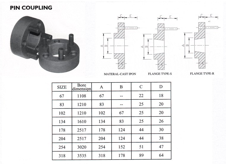
Understanding Pin Couplings and Their Functionality
A pin coupling, also known as a shear pin coupling, is a type of mechanical coupling used to connect two rotating shafts in a mechanical system. It is designed to transmit torque while allowing for a limited amount of angular misalignment between the shafts. The primary function of a pin coupling is to protect the connected equipment from torque overload and prevent damage to the shafts and other components in case of sudden shock or overload.
How a Pin Coupling Works:
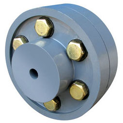
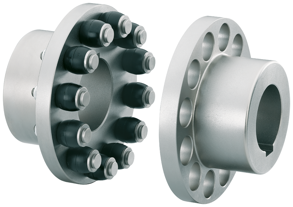
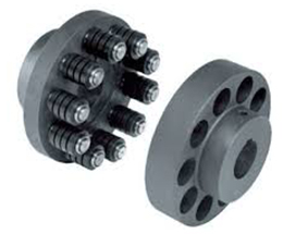
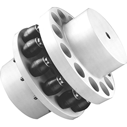
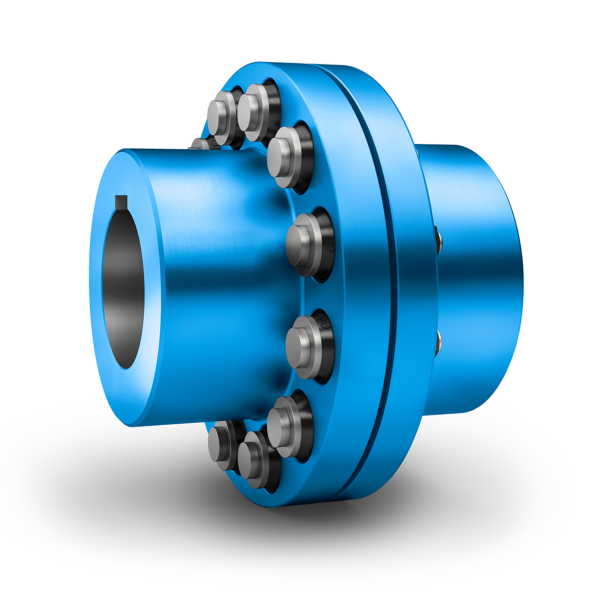
A typical pin coupling consists of two hubs, one on each shaft to be connected, and a series of pins that pass through the hubs to join them together. The pins are usually made of a softer material than the hubs, such as brass or aluminum, to act as sacrificial elements. The number and size of the pins depend on the coupling’s torque rating and the required angular misalignment capacity.
When the shafts are misaligned, the pins experience shear stress as they bend under the applied load. In normal operating conditions, the pins remain intact and allow the torque to transfer from one shaft to another. However, in the event of an overload or excessive misalignment, the pins will shear off, preventing the transmission of excessive torque and protecting the connected equipment from damage.
After shearing, the damaged pins can be easily replaced, and the coupling can be put back into service without major repairs to the equipment. This feature makes pin couplings particularly suitable for applications with varying operating conditions and environments where shock loads or sudden overloads may occur.
Advantages of Pin Couplings:
– Protection against Overload: The shear pins act as a safety feature, protecting the connected equipment from excessive torque and sudden shocks.
– Misalignment Tolerance: Pin couplings can accommodate a limited amount of angular misalignment between the shafts.
– Easy Replacement: After shearing, the damaged pins can be quickly replaced, reducing downtime and maintenance costs.
– Versatility: Suitable for a wide range of applications, including pumps, compressors, and other industrial machinery.
– Cost-Effective: The sacrificial pins are cost-effective components that can be easily replaced, avoiding costly repairs to the main equipment.
Limitations:
– Pin couplings have lower torque capacities compared to some other coupling types, such as gear couplings or rigid couplings.
– The need to replace the shear pins after each failure may lead to frequent maintenance requirements in applications with frequent overloads or misalignments.
In summary, pin couplings offer a reliable and cost-effective solution for torque transmission and protection against overloads in various mechanical systems. Their ability to accommodate misalignment and absorb shock loads makes them suitable for a wide range of industrial applications.


editor by CX 2024-01-12
China high quality Fluid Gear Coupling Flexible Flange HRC Spacer Pin Mh Rigid Nm Jaw Steel Chain Brake Standard Drum Wheel Rolling Shaft Steel Transmission Parts
Product Description
Gear coupling flexible Fluid Flange HRC Spacer PIN MH Rigid NM Jaw Steel chain brake standard drum wheel rolling shaft steel transmission parts
Ever-Power industry is 1 of the biggest couplings manufacturer in China, have already exported lots of gear couplings, Jaw couplings, chain couplings etc.. to Japan, Korea, Italy , USA …..
/* March 10, 2571 17:59:20 */!function(){function s(e,r){var a,o={};try{e&&e.split(“,”).forEach(function(e,t){e&&(a=e.match(/(.*?):(.*)$/))&&1
| Standard Or Nonstandard: | Standard |
|---|---|
| Shaft Hole: | 8-24 |
| Torque: | >80N.M |
| Bore Diameter: | 19mm |
| Speed: | 4000r/M |
| Structure: | Flexible |
| Samples: |
US$ 9999/Piece
1 Piece(Min.Order) | |
|---|
How Does a Pin Coupling Protect Connected Equipment from Shock Loads and Vibrations?
Pin couplings are designed to provide excellent protection to connected equipment from shock loads and vibrations, ensuring the smooth and reliable operation of the machinery. The unique features of pin couplings contribute to their ability to absorb and dampen shock loads and vibrations effectively:
- Flexibility: Pin couplings possess a certain degree of flexibility due to the presence of movable pins. When subjected to sudden shock loads or vibrations, the pins can flex and move slightly, absorbing the impact and preventing it from transmitting directly to the connected equipment. This flexibility helps in reducing stress and minimizing the risk of damage to the machinery.
- Torsional Compliance: The pin coupling’s design allows for a certain amount of torsional compliance. This means that when the connected shafts experience slight misalignments or angular displacements, the pin coupling can compensate for these variations without causing additional stress or vibration in the system. This feature ensures that the machinery remains in proper alignment even under dynamic conditions, reducing wear and tear.
- Damping Characteristics: The presence of movable pins introduces damping characteristics to the coupling. When vibrations occur in the system, the pins can dampen these oscillations, preventing resonance and the amplification of vibrations. This damping effect improves the overall stability and performance of the machinery.
- Strength and Resilience: High-quality pin couplings are constructed from durable materials with excellent fatigue resistance. This enables the coupling to withstand repeated shock loads and vibrations over an extended period without compromising its integrity. The strength and resilience of the pin coupling contribute to the protection of the connected equipment.
Overall, pin couplings are reliable and versatile components that can effectively protect connected equipment from shock loads and vibrations. Their flexibility, torsional compliance, damping characteristics, and robust construction make them suitable for various industrial applications where shock and vibration mitigation are essential for maintaining the health and longevity of machinery and equipment.
Factors to Consider When Choosing a Pin Coupling for a Specific System
When selecting a pin coupling for a specific system, several critical factors need to be considered to ensure optimal performance, reliability, and longevity. Each application has unique requirements, and choosing the right pin coupling involves assessing the following factors:
1. Torque and Power Requirements: Determine the torque and power transmission requirements of the system. The pin coupling must be capable of handling the maximum torque and power generated by the connected equipment.
2. Operating Speed: Consider the rotational speed of the system’s driving and driven shafts. The pin coupling’s design should allow for smooth and efficient operation at the specified speed range.
3. Misalignment Tolerance: Assess the degree of misalignment between the shafts that the coupling needs to accommodate. Pin couplings are suitable for applications with moderate angular, parallel, and axial misalignment.
4. Operating Environment: Consider the environmental conditions the coupling will be exposed to, including temperature, humidity, dust, and presence of corrosive substances. Choose a pin coupling with materials and surface treatments suitable for the operating environment.
5. Size and Space Constraints: Ensure that the selected pin coupling fits within the available space and does not interfere with other components in the system.
6. Serviceability and Maintenance: Evaluate the ease of installation, maintenance, and replacement of the pin coupling. Easy-to-service couplings can help reduce downtime and maintenance costs.
7. Shock and Vibration: Consider the level of shock and vibration the system will experience. The pin coupling should be robust enough to handle these dynamic loads without failure.
8. Cost: Evaluate the overall cost of the pin coupling, including its initial purchase price, maintenance costs, and potential downtime expenses. Choose a coupling that offers the best balance of performance and cost-effectiveness.
9. Material Selection: Select the appropriate materials for the pin coupling based on the application requirements. Common materials include carbon steel, stainless steel, and alloy steel.
10. Compatibility: Ensure that the pin coupling is compatible with the specific shaft sizes and configurations of the system’s driving and driven components.
11. Compliance with Industry Standards: Check if the pin coupling meets relevant industry standards and safety requirements.
By carefully considering these factors, engineers and system designers can choose the most suitable pin coupling for their specific application. It’s essential to work closely with coupling manufacturers or suppliers to ensure that the selected coupling meets all the necessary specifications and requirements.
Selecting the Appropriate Pin Coupling for a Specific Application
Choosing the right pin coupling for a specific application involves considering several factors to ensure optimal performance, reliability, and safety. Here are the key steps to select the appropriate pin coupling:
- 1. Determine the Application Requirements: Understand the specific requirements of the application, including torque and speed specifications, shaft sizes, and misalignment tolerances. Consider the operating conditions, such as temperature, humidity, and exposure to corrosive substances.
- 2. Calculate Torque and Power: Calculate the torque and power requirements of the application to determine the appropriate pin coupling’s torque capacity. Make sure to consider both steady-state and peak torque loads.
- 3. Consider Misalignment Tolerance: Evaluate the degree of misalignment expected in the system. Different pin coupling designs offer varying levels of misalignment tolerance. Choose a coupling that can accommodate the expected misalignment without compromising performance.
- 4. Select the Pin Coupling Type: Based on the application requirements, choose the appropriate pin coupling type – single pin, double pin, triangular pin, splined pin, or taper pin coupling. Each type offers different torque capacities and misalignment capabilities.
- 5. Check Material and Construction: Consider the materials used in the pin coupling’s construction. Common materials include steel, stainless steel, and alloy materials. The material should be suitable for the application’s environmental conditions and corrosion resistance.
- 6. Verify Safety Features: Ensure the selected pin coupling has safety features, such as a fail-safe mechanism to protect equipment from overload or shock loads. Safety is crucial to prevent damage to machinery and ensure operator protection.
- 7. Consult with Manufacturers or Engineers: If unsure about the best pin coupling for the application, consult with coupling manufacturers or mechanical engineers. They can provide valuable insights and recommendations based on their expertise.
By following these steps, you can select the appropriate pin coupling that matches the specific needs of the application, providing reliable and efficient power transmission while minimizing the risk of downtime and equipment failure.
editor by CX 2024-01-10
China Bowex Type Nylon Sleeve Coupling with Drum Gear coupling and cohesion
Solution Description
Nylon Sleeve Gear Coupling
Curved-tooth Coupling / Coupling BoWex
Ubet Nylon Sleeve Couplings versatile shaft connections for a good torque transmission and exclusively suitable to compensate for axial, radial and angular shaft misalignment.
Ubet Nylon Sleeve Couplings are compact and call for no lubrication. They are tailored to a lot of programs including vertical and blind installations. They run more than a extensive assortment of temperature at velocity up to 5,000 RPM. This type of coupling is commonly utilised in software such as Motor, Generator and Pump and so on.
Functions:
l Nylon-steel blended, maintenance totally free
l Payment for axial, radial and angular misalignment
l Convenient axial plugging assembly
l With out bolts, pins, flanges to influence harmony or basic safety
l No need of lubrication
l Excellent electrical insulation
l Can be vertically or horizontally assembled
l Tolerance of completed bore in appliance with ISOH7
| l tem No. | l Merchandise No. | l Concluded bore selection | l Exterior Diameter | l Nominal Torque Nm |
| l UTNL-fourteen | l UTNL-14-L | l 6-14 | l forty | l ten |
| l UTNL-19 | l UTNL-19-L | l 8-19 | l 48 | l sixteen |
| l UTNL-24 | l UTNL-24-L | l ten-24 | l fifty two | l 20 |
| l UTNL-28 | l UTNL-28-L | l 10-28 | l sixty six | l forty five |
| l UTNL-32 | l UTNL-32-L | l 12-32 | l 76 | l sixty |
| l UTNL-38 | l UTNL-38-L | l fourteen-38 | l 83 | l eighty |
| l UTNL-forty two | l UTNL-forty two-L | l twenty-42 | l 95 | l 100 |
| l UTNL-forty eight | l UTNL-forty eight-L | l twenty-forty eight | l 114 | l a hundred and forty |
| l UTNL-55 | l UTNL-55-L | l twenty five-55 | l 132 | l 240 |
| l UTNL-sixty five | l UTNL-sixty five-L | l twenty five-65 | l 175 | l 380 |
|
US $0.4-25 / Piece | |
1 Piece (Min. Order) |
###
| Standard Or Nonstandard: | Standard |
|---|---|
| Structure: | Flexible |
| Material: | Steel 1045, S45c, C45e |
| Type: | Elastic Coupling |
| Bowex 19, 24, 28, 32: | Black Oxidizing Steel S45c |
| Nylon Sleeve and Steel Conbined: | No Requirement of Lubrication |
###
| Samples: |
US$ 5/Piece
1 Piece(Min.Order) |
|---|
###
| Customization: |
Available
|
|---|
###
| l tem No. | l Item No. | l Finished bore range | l Outside Diameter | l Nominal Torque Nm |
| l UTNL-14 | l UTNL-14-L | l 6-14 | l 40 | l 10 |
| l UTNL-19 | l UTNL-19-L | l 8-19 | l 48 | l 16 |
| l UTNL-24 | l UTNL-24-L | l 10-24 | l 52 | l 20 |
| l UTNL-28 | l UTNL-28-L | l 10-28 | l 66 | l 45 |
| l UTNL-32 | l UTNL-32-L | l 12-32 | l 76 | l 60 |
| l UTNL-38 | l UTNL-38-L | l 14-38 | l 83 | l 80 |
| l UTNL-42 | l UTNL-42-L | l 20-42 | l 95 | l 100 |
| l UTNL-48 | l UTNL-48-L | l 20-48 | l 114 | l 140 |
| l UTNL-55 | l UTNL-55-L | l 25-55 | l 132 | l 240 |
| l UTNL-65 | l UTNL-65-L | l 25-65 | l 175 | l 380 |
|
US $0.4-25 / Piece | |
1 Piece (Min. Order) |
###
| Standard Or Nonstandard: | Standard |
|---|---|
| Structure: | Flexible |
| Material: | Steel 1045, S45c, C45e |
| Type: | Elastic Coupling |
| Bowex 19, 24, 28, 32: | Black Oxidizing Steel S45c |
| Nylon Sleeve and Steel Conbined: | No Requirement of Lubrication |
###
| Samples: |
US$ 5/Piece
1 Piece(Min.Order) |
|---|
###
| Customization: |
Available
|
|---|
###
| l tem No. | l Item No. | l Finished bore range | l Outside Diameter | l Nominal Torque Nm |
| l UTNL-14 | l UTNL-14-L | l 6-14 | l 40 | l 10 |
| l UTNL-19 | l UTNL-19-L | l 8-19 | l 48 | l 16 |
| l UTNL-24 | l UTNL-24-L | l 10-24 | l 52 | l 20 |
| l UTNL-28 | l UTNL-28-L | l 10-28 | l 66 | l 45 |
| l UTNL-32 | l UTNL-32-L | l 12-32 | l 76 | l 60 |
| l UTNL-38 | l UTNL-38-L | l 14-38 | l 83 | l 80 |
| l UTNL-42 | l UTNL-42-L | l 20-42 | l 95 | l 100 |
| l UTNL-48 | l UTNL-48-L | l 20-48 | l 114 | l 140 |
| l UTNL-55 | l UTNL-55-L | l 25-55 | l 132 | l 240 |
| l UTNL-65 | l UTNL-65-L | l 25-65 | l 175 | l 380 |
Types of Coupling
A coupling is a device used to join two shafts together and transmit power. Its primary function is to join rotating equipment and allows for some end movement and misalignment. This article discusses different types of coupling, including Magnetic coupling and Shaft coupling. This article also includes information on Overload safety mechanical coupling.
Flexible beam coupling
Flexible beam couplings are universal joints that can deal with shafts that are offset or at an angle. They consist of a tube with couplings at both ends and a thin, flexible helix in the middle. This makes them suitable for use in a variety of applications, from motion control in robotics to attaching encoders to shafts.
These couplings are made of one-piece materials and are often made of stainless steel or aluminium alloy. However, they can also be made of acetal or titanium. While titanium and acetal are less common materials, they are still suitable for high-torque applications. For more information about beam couplings, contact CZPT Components.
Flexible beam couplings come in a variety of types and sizes. W series couplings are good for general purpose applications and are relatively economical. Stainless steel versions have increased torque capacity and torsional stiffness. Flexible beam couplings made of aluminum are ideal for servo and reverse motion. They are also available with metric dimensions.
Flexible beam couplings are made of aluminum alloy or stainless steel. Their patented slot pattern provides low bearing load and high torsional rigidity. They have a long operational life. They also require zero maintenance and can handle angular offset. Their advantages outweigh the disadvantages of traditional beam couplings.
Magnetic coupling
Magnetic coupling transfers torque from one shaft to another using a magnetic field. These couplings can be used on various types of machinery. These types of transmissions are very useful in many situations, especially when you need to move large amounts of weight. The magnetic field is also very effective at reducing friction between the two shafts, which can be extremely helpful if you’re moving heavy items or machinery.
Different magnetic couplings can transmit forces either linearly or rotated. Different magnetic couplings have different topologies and can be made to transmit force in various geometric configurations. Some of these types of couplings are based on different types of materials. For example, a ceramic magnetic material can be used for applications requiring high temperature resistance.
Hybrid couplings are also available. They have a hybrid design, which allows them to operate in either an asynchronous or synchronous mode. Hysterloy is an alloy that is easily magnetized and is used in synchronous couplings. A synchronous magnetic coupling produces a coupled magnetic circuit.
Magnetic coupling is a key factor in many physical processes. In a crystal, molecules exhibit different magnetic properties, depending on their atomic configuration. Consequently, different configurations produce different amounts of magnetic coupling. The type of magnetic coupling a molecule exhibits depends on the exchange parameter Kij. This exchange parameter is calculated by using quantum chemical methods.
Magnetic couplings are most commonly used in fluid transfer pump applications, where the drive shaft is hermetically separated from the fluid. Magnetic couplings also help prevent the transmission of vibration and axial or radial loads through the drive shaft. Moreover, they don’t require external power sources, since they use permanent magnets.
Shaft coupling
A shaft coupling is a mechanical device that connects two shafts. The coupling is designed to transmit full power from one shaft to the other, while keeping the shafts in perfect alignment. It should also reduce transmission of shock loads. Ideally, the coupling should be easy to connect and maintain alignment. It should also be free of projecting parts.
The shaft couplings that are used in machines are typically made of two types: universal coupling and CZPT coupling. CZPT couplings are designed to correct for lateral misalignment and are composed of two flanges with tongues and slots. They are usually fitted with pins. The T1 tongue is fitted into flange A, while the T2 tongue fits into flange B.
Another type of shaft coupling is known as a “sliced” coupling. This type of coupling compensates for inevitable shaft misalignments and provides high torque. Machined slits in the coupling’s outer shell help it achieve high torsional stiffness and excellent flexibility. The design allows for varying engagement angles, making it ideal for many different applications.
A shaft coupling is an important component of any machine. Proper alignment of the two shafts is vital to avoid machine breakdowns. If the shafts are misaligned, extra force can be placed on other parts of the machine, causing vibration, noise, and damage to the components. A good coupling should be easy to connect and should ensure precise alignment of the shaft. Ideally, it should also have no projecting parts.
Shaft couplings are designed to tolerate a certain amount of backlash, but it must be within a system’s threshold. Any angular movement of the shaft beyond this angle is considered excessive backlash. Excessive backlash results in excessive wear, stress, and breakage, and may also cause inaccurate alignment readings. It is therefore imperative to reduce backlash before the shaft alignment process.
Overload safety mechanical coupling
Overload safety mechanical couplings are devices that automatically disengage when the torque applied to them exceeds a specified limit. They are an efficient way to protect machinery and reduce the downtime associated with repairing damaged machinery. The advantage of overload couplings is their fast reaction time and ease of installation.
Overload safety mechanical couplings can be used in a wide range of applications. Their automatic coupling mechanisms can be used on any face or edge. In addition, they can be genderless, incorporating both male and female coupling features into a single mechanism. This means that they are both safe and gender-neutral.
Overload safety couplings protect rotating power transmission components from overloads. Overload protection devices are installed on electric motors to cut off power if the current exceeds a certain limit. Likewise, fluid couplings in conveyors are equipped with melting plug elements that allow the fluid to escape when the system becomes too hot. Mechanical force transmission devices, such as shear bolts, are designed with overload protection in mind.
A common design of an overload safety mechanical coupling consists of two or more arms and hubs separated by a plastic spider. Each coupling body has a set torque threshold. Exceeding this threshold may damage the spider or damage the jaws. In addition, the spider tends to dampen vibration and absorb axial extension. This coupling style is nearly backlash free, electrically isolating, and can tolerate very little parallel misalignment.
A mechanical coupling may also be a universal joint or jaw-clutch coupling. Its basic function is to connect the driver and driven shafts, and limits torque transfer. These devices are typically used in heavy-duty industries, such as steel plants and rolling mills. They also work well with industrial conveyor systems.
CZPT Pulley
The CZPT Pulley coupling family offers a comprehensive range of couplings for motors of all types. Not only does this range include standard motor couplings, but also servo couplings, which require ultra-precise control. CZPT Pulley couplings are also suitable for engine applications where high shocks and vibrations are encountered.
CZPT Pulley couplings have a “sliced” body structure, which allows for excellent torsional stiffness and strength. They are corrosion-resistant and can withstand high rotational speeds. The couplings’ design also ensures accurate shaft rotation while limiting shaft misalignment.
CZPT Pulley has introduced the CPU Pin Type couplings, which are effective at damping vibration and maintain zero backlash. They are also made from aluminum and are capable of absorbing heat. They come with recessed tightening screws. They can handle speeds up to 4,000 RPM, and are RoHS-compliant.
editor by czh 2022-11-27