Product Description
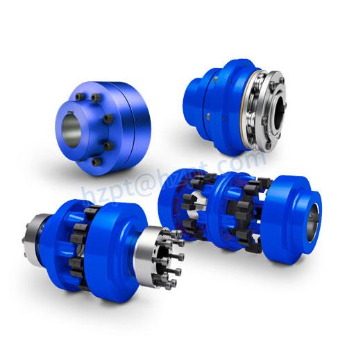
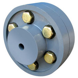
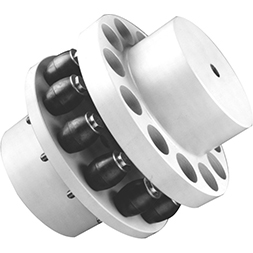
Hl Type Flexible Muff Flange Bush Flexible Elastic Sleeve Oldham Steel Disc Clamp Shaft Rigid Fcl Pin Coupling With Brake WHEEL
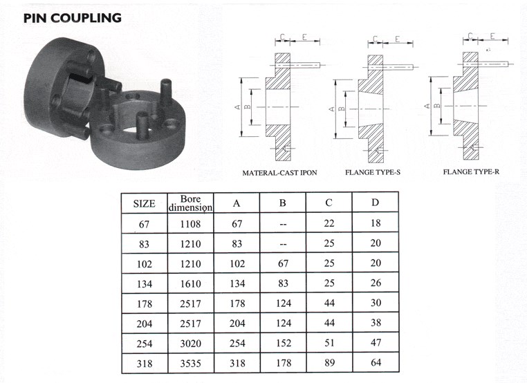
The characteristics of FCL Flexible Pin & Bush Coupling
(1)Coupling is simple in structure, convenient installation, easy replacement, small size, light weight.
(2)If the installation adjustment can keep 2 relative displacement within the prescribed limits, then coupling will have satisfactory performance and long service life.
(3) It can be widely applied to all kinds of medium and small power transmission shafts, such as reducer, crane, compressor, conveyor, textile machine, hoist and ball mill, which are not loaded by motors.
(4)The allowable relative displacement of the elastic sleeve pin couplings:
Radial displacement: 0.2~0.6mm angular displacement: 0 ° 30 ‘~1° 30’
Related products:
Production workshop:
Company information:
| Standard Or Nonstandard: | Standard |
|---|---|
| Shaft Hole: | 19-32 |
| Torque: | >80N.M |
| Bore Diameter: | 19mm |
| Speed: | 4000r/M |
| Structure: | Flexible |
| Samples: |
US$ 9999/Piece
1 Piece(Min.Order) | |
|---|
Can Pin Couplings Accommodate High Torque and High-Speed Applications?
Pin couplings are versatile and robust, making them suitable for a wide range of applications, including those involving high torque and high-speed requirements. However, the specific design and construction of the pin coupling will determine its capacity to handle such demanding conditions.
The ability of a pin coupling to accommodate high torque depends on factors such as the material used, the size and number of pins, and the overall design. High-quality pin couplings are often made from strong and durable materials like alloy steel, which allows them to withstand significant torque loads without failure or deformation.
Similarly, the capability of a pin coupling to handle high speeds depends on factors such as the balance of the coupling and the precise manufacturing of the pins and hubs. Properly balanced pin couplings can operate at higher speeds without generating excessive vibration or causing premature wear.
When selecting a pin coupling for high torque and high-speed applications, it is essential to consider the following:
- Design and Construction: Opt for pin couplings with a robust and well-engineered design to handle the expected torque and speed requirements.
- Material: Choose pin couplings made from high-quality materials known for their strength and fatigue resistance.
- Size: Select an appropriate size of pin coupling that can accommodate the torque and speed expected in the application.
- Manufacturer’s Ratings: Refer to the manufacturer’s specifications and torque-speed curves to ensure the coupling meets the desired performance criteria.
By carefully considering these factors and choosing a pin coupling designed for high torque and high-speed applications, you can ensure reliable and efficient power transmission in demanding industrial settings.
How Does a Pin Coupling Handle Angular, Parallel, and Axial Misalignment?
A pin coupling is designed to handle different types of misalignment, including angular, parallel, and axial misalignment. The unique construction of pin couplings allows them to accommodate these misalignments without compromising the efficiency and performance of the connected equipment.
1. Angular Misalignment: Angular misalignment occurs when the axes of the driving and driven shafts are not parallel but intersect at an angle. Pin couplings can tolerate angular misalignment because of their flexible and floating pin design. The two coupling halves are connected by a series of pins, which can pivot and move within the pin holes. This flexibility allows the coupling to bend slightly, adjusting to the angle of misalignment between the shafts.
2. Parallel Misalignment: Parallel misalignment happens when the axes of the driving and driven shafts are parallel, but they are laterally displaced from each other. Pin couplings can handle parallel misalignment to some extent due to the floating nature of the pins. The pins can move laterally within the pin holes, allowing the coupling to adapt to the offset between the shafts.
3. Axial Misalignment: Axial misalignment occurs when there is a linear displacement along the axis of one shaft concerning the other. While pin couplings primarily focus on handling angular and parallel misalignment, they may offer limited axial misalignment capabilities. The floating pins provide a small degree of axial movement, but excessive axial misalignment is best avoided to prevent additional stresses on the coupling.
It is important to note that while pin couplings can accommodate some degree of misalignment, excessive misalignment should be avoided to prevent premature wear and potential failure of the coupling and connected equipment. Regular inspection and maintenance can help identify and address any misalignment issues, ensuring the optimal performance and longevity of the pin coupling in power transmission applications.
Types of Pin Coupling Designs
Pin couplings, also known as shear pin couplings, come in various designs to suit different application requirements. The main types of pin coupling designs are as follows:
- 1. Single Pin Coupling: In this design, a single shear pin is used to connect the two shafts. The pin is placed in a hole that runs through both coupling halves. Under excessive torque or shock loads, the pin shears off, disconnecting the shafts and protecting the equipment from damage. Single pin couplings are commonly used in light to moderate-duty applications.
- 2. Double Pin Coupling: Double pin couplings use two shear pins that are positioned 180 degrees apart. This design provides increased torque capacity and improved balance compared to the single pin design. Double pin couplings are suitable for applications with higher torque requirements.
- 3. Triangular Pin Coupling: Triangular pin couplings use three pins arranged in a triangular pattern around the circumference of the coupling. This design offers even higher torque capacity and improved torsional stiffness. Triangular pin couplings are ideal for heavy-duty applications where higher torque and misalignment tolerance are essential.
- 4. Splined Pin Coupling: Splined pin couplings use splines instead of solid pins to transmit torque between the shafts. The splines provide a more secure connection and better torque transmission compared to solid pins. Splined pin couplings are commonly used in precision motion control applications.
- 5. Taper Pin Coupling: Taper pin couplings use tapered pins that wedge tightly into matching tapered holes in the coupling halves. This design offers excellent torque transmission and alignment capabilities. Taper pin couplings are often used in heavy machinery and power transmission systems.
Each type of pin coupling design has its advantages and limitations, and the selection depends on factors such as the application’s torque requirements, misalignment tolerance, and environmental conditions. It is essential to choose the right type of pin coupling to ensure optimal performance, reliability, and safety in the mechanical system.


editor by CX 2023-09-06