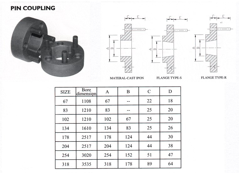
Product Description
Elastic Pin Shaft Coupling
ZLL type with the brake wheel elastic cylinder pin tooth coupling maintenance is convenient, life is long, remove the file board can replace nylon column pin. Nylon pin is a self – lubricating material, it is not necessary to lubricate, it can not only save the lubricating oil, but also clean the working environment.
Elastic pin coupling with pin is made into a plurality of non-metallic materials, placed between the 2 half couplings and the outer ring of the inner surface of the hole, the pin transfer torque to achieve the 2 halves of the coupling, the coupling has the following features:
1. the transmission torque is big, when the rotating diameter of the same torque is smaller than that of the gear type coupling, small size, light weight, can be partially replaced by the gear type coupling.
2.compared with the gear coupling structure, the elastic pin tooth type connector is simple, less components, convenient manufacture, no gear cutting machine.
3. the elastic pin tooth type coupling and easy maintenance, long service life, remove the plate to replace the nylon pin.
4. the elastic pin tooth type coupling nylon pin for self-lubricating materials, no lubrication, not only saves the lubricating oil, and clean work environment.
5. the kinetic energy damping elastic pin tooth type coupling, large noise.
ZLL type with the brake wheel elastic cylinder pin tooth coupling maintenance is convenient, life is long, remove the file board can replace nylon column pin. Nylon pin is a self – lubricating material, it is not necessary to lubricate, it can not only save the lubricating oil, but also clean the working environment.
|
Model |
Tn(N.m) |
[n]r/min |
D |
|
D0 |
D |
B |
S |
Kg.m2 |
m |
||
|
Y |
J1 |
|||||||||||
|
d1 |
d2 |
L |
L1 |
|||||||||
|
ZLL1 |
250 |
4000 |
42 |
30 |
160 |
98 |
68 |
3.5 |
0.571 |
7 |
||
|
52 |
38 |
|||||||||||
|
25 28 |
25 28 |
62 |
44 |
|||||||||
|
30 32 |
82 |
60 |
||||||||||
|
ZLL2 |
630 |
3800 |
25 28 |
25 28 |
62 |
44 |
200 |
124 |
85 |
5 |
0.063 |
12.6 |
|
82 |
60 |
|||||||||||
|
40 42 |
112 |
84 |
||||||||||
|
ZLL3 |
1600 |
3000 |
112 |
84 |
250 |
166 |
105 |
5 |
0.24 |
30.4 |
||
|
60 |
142 |
107 |
||||||||||
|
ZLL4 |
4000 |
2400 |
112 |
84 |
315 |
214 |
132 |
5 |
0.65 |
52.4 |
||
|
71 75 |
71 75 |
142 |
107 |
|||||||||
|
80 |
172 |
132 |
||||||||||
|
ZLL5 |
6300 |
1900 |
142 |
107 |
400 |
240 |
168 |
7 |
1.63 |
81.3 |
||
|
172 |
132 |
|||||||||||
|
ZLL6 |
10000 |
1500 |
142 |
107 |
500 |
280 |
210 |
7 |
4.4 |
139.8 |
||
|
172 |
132 |
|||||||||||
|
212 |
167 |
|||||||||||
|
ZLL7 |
16000 |
1200 |
172 |
132 |
630 |
330 |
265 |
9 |
12.8 |
257 |
||
|
212 |
167 |
|||||||||||
|
130 |
130 |
252 |
202 |
|||||||||
|
ZLL8 |
25000 |
1050 |
90 95 |
90 95 |
172 |
132 |
710 |
370 |
298 |
9 |
20.9 |
331 |
|
212 |
167 |
|||||||||||
|
252 |
202 |
|||||||||||
|
302 |
242 |
|||||||||||
|
ZLL9 |
31500 |
950 |
212 |
167 |
800 |
384 |
335 |
11 |
33.5 |
424 |
||
|
252 |
202 |
|||||||||||
|
160 170 |
160 170 |
302 |
242 |
|||||||||
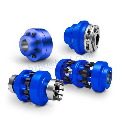
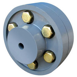
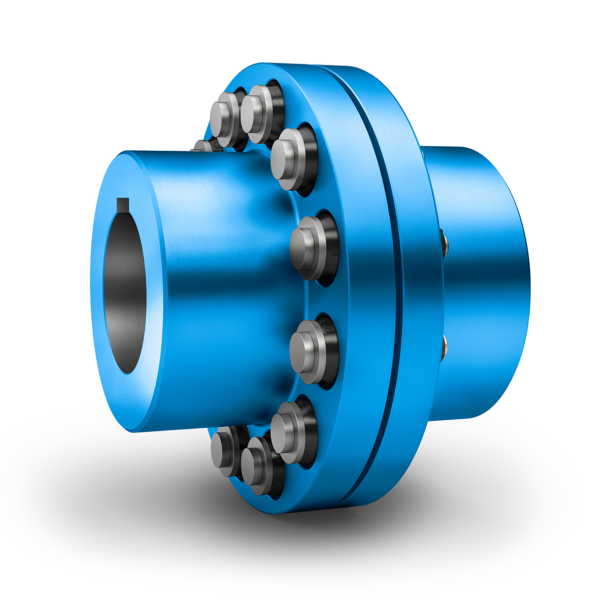
Product Pictures
♦Other Products List
| Transmission Machinery Parts Name |
Model |
| Universal Coupling | WS,WSD,WSP |
| Cardan Shaft | SWC,SWP,SWZ |
| Tooth Coupling | CL,CLZ,GCLD,GIICL, GICL,NGCL,GGCL,GCLK |
| Disc Coupling | JMI,JMIJ,JMII,JMIIJ |
| High Flexible Coupling | LM |
| Chain Coupling | GL |
| Jaw Coupling | LT |
| Grid Coupling | JS |
♦Our Company
HangZhou CHINAMFG Machinery Manufacturing Co., Ltd. is a technology-based company specializing in the design and manufacture of basic transmission parts and various auxiliary non-standard equipment accessories. The products are mainly used in metallurgy, electric power, mining, chemical industry, petroleum, papermaking, shipbuilding, heavy industry, etc.
In many industries, it has provided strong technical and equipment support for many companies around the world. At present, the products are also exported to Russia, Italy, Spain, Brazil, Ukraine, Turkey, Australia, Singapore, Vietnam, Indonesia, Malaysia, Sri Lanka and other countries and regions.
Welcome to customize products from our factory and please provide your design drawings or contact us if you need other requirements.
♦Our Services
1.Design Services
Our design team has experience in cardan shaft relating to product design and development. If you have any needs for your new product or wish to make further improvements, we are here to offer our support.
2.Product Services
raw materials → Cutting → Forging →Rough machining →Shot blasting →Heat treatment →Testing →Fashioning →Cleaning→ Assembly→Packing→Shipping
3.Samples Procedure
We could develop the sample according to your requirement and amend the sample constantly to meet your need.
4.Research & Development
We usually research the new needs of the market and develop the new model when there is new cars in the market.
5.Quality Control
Every step should be special test by Professional Staff according to the standard of ISO9001 and TS16949.
♦FAQ
Q 1: Are you trading company or manufacturer?
A: We are a professional manufacturer specializing in manufacturing
various series of couplings.
Q 2:Can you do OEM?
Yes, we can. We can do OEM & ODM for all the customers with customized artworks of PDF or AI format.
Q 3:How long is your delivery time?
Generally it is 20-30 days if the goods are not in stock. It is according to quantity.
Q 4: Do you provide samples ? Is it free or extra ?
Yes, we could offer the sample but not for free.Actually we have a very good price principle, when you make the bulk order then cost of sample will be deducted.
Q 5: How long is your warranty?
A: Our Warranty is 12 month under normal circumstance.
Q 6: What is the MOQ?
A:Usually our MOQ is 1pcs.
Q 7: Do you have inspection procedures for coupling ?
A:100% self-inspection before packing.
Q 8: Can I have a visit to your factory before the order?
A: Sure,welcome to visit our factory.
Q 9: What’s your payment?
A:1) T/T.
♦Contact Us
Add: No.11 HangZhou Road,Chengnan park,HangZhou City,ZheJiang Province,China
| Standard Or Nonstandard: | Standard |
|---|---|
| Shaft Hole: | 19-32 |
| Torque: | 250n.M |
| Bore Diameter: | 102mm |
| Speed: | 4000r/M |
| Structure: | Flexible |
| Customization: |
Available
| Customized Request |
|---|
Can Pin Couplings Accommodate High Torque and High-Speed Applications?
Pin couplings are versatile and robust, making them suitable for a wide range of applications, including those involving high torque and high-speed requirements. However, the specific design and construction of the pin coupling will determine its capacity to handle such demanding conditions.
The ability of a pin coupling to accommodate high torque depends on factors such as the material used, the size and number of pins, and the overall design. High-quality pin couplings are often made from strong and durable materials like alloy steel, which allows them to withstand significant torque loads without failure or deformation.
Similarly, the capability of a pin coupling to handle high speeds depends on factors such as the balance of the coupling and the precise manufacturing of the pins and hubs. Properly balanced pin couplings can operate at higher speeds without generating excessive vibration or causing premature wear.
When selecting a pin coupling for high torque and high-speed applications, it is essential to consider the following:
- Design and Construction: Opt for pin couplings with a robust and well-engineered design to handle the expected torque and speed requirements.
- Material: Choose pin couplings made from high-quality materials known for their strength and fatigue resistance.
- Size: Select an appropriate size of pin coupling that can accommodate the torque and speed expected in the application.
- Manufacturer’s Ratings: Refer to the manufacturer’s specifications and torque-speed curves to ensure the coupling meets the desired performance criteria.
By carefully considering these factors and choosing a pin coupling designed for high torque and high-speed applications, you can ensure reliable and efficient power transmission in demanding industrial settings.
How Does a Pin Coupling Handle Angular, Parallel, and Axial Misalignment?
A pin coupling is designed to handle different types of misalignment, including angular, parallel, and axial misalignment. The unique construction of pin couplings allows them to accommodate these misalignments without compromising the efficiency and performance of the connected equipment.
1. Angular Misalignment: Angular misalignment occurs when the axes of the driving and driven shafts are not parallel but intersect at an angle. Pin couplings can tolerate angular misalignment because of their flexible and floating pin design. The two coupling halves are connected by a series of pins, which can pivot and move within the pin holes. This flexibility allows the coupling to bend slightly, adjusting to the angle of misalignment between the shafts.
2. Parallel Misalignment: Parallel misalignment happens when the axes of the driving and driven shafts are parallel, but they are laterally displaced from each other. Pin couplings can handle parallel misalignment to some extent due to the floating nature of the pins. The pins can move laterally within the pin holes, allowing the coupling to adapt to the offset between the shafts.
3. Axial Misalignment: Axial misalignment occurs when there is a linear displacement along the axis of one shaft concerning the other. While pin couplings primarily focus on handling angular and parallel misalignment, they may offer limited axial misalignment capabilities. The floating pins provide a small degree of axial movement, but excessive axial misalignment is best avoided to prevent additional stresses on the coupling.
It is important to note that while pin couplings can accommodate some degree of misalignment, excessive misalignment should be avoided to prevent premature wear and potential failure of the coupling and connected equipment. Regular inspection and maintenance can help identify and address any misalignment issues, ensuring the optimal performance and longevity of the pin coupling in power transmission applications.
Selecting the Appropriate Pin Coupling for a Specific Application
Choosing the right pin coupling for a specific application involves considering several factors to ensure optimal performance, reliability, and safety. Here are the key steps to select the appropriate pin coupling:
- 1. Determine the Application Requirements: Understand the specific requirements of the application, including torque and speed specifications, shaft sizes, and misalignment tolerances. Consider the operating conditions, such as temperature, humidity, and exposure to corrosive substances.
- 2. Calculate Torque and Power: Calculate the torque and power requirements of the application to determine the appropriate pin coupling’s torque capacity. Make sure to consider both steady-state and peak torque loads.
- 3. Consider Misalignment Tolerance: Evaluate the degree of misalignment expected in the system. Different pin coupling designs offer varying levels of misalignment tolerance. Choose a coupling that can accommodate the expected misalignment without compromising performance.
- 4. Select the Pin Coupling Type: Based on the application requirements, choose the appropriate pin coupling type – single pin, double pin, triangular pin, splined pin, or taper pin coupling. Each type offers different torque capacities and misalignment capabilities.
- 5. Check Material and Construction: Consider the materials used in the pin coupling’s construction. Common materials include steel, stainless steel, and alloy materials. The material should be suitable for the application’s environmental conditions and corrosion resistance.
- 6. Verify Safety Features: Ensure the selected pin coupling has safety features, such as a fail-safe mechanism to protect equipment from overload or shock loads. Safety is crucial to prevent damage to machinery and ensure operator protection.
- 7. Consult with Manufacturers or Engineers: If unsure about the best pin coupling for the application, consult with coupling manufacturers or mechanical engineers. They can provide valuable insights and recommendations based on their expertise.
By following these steps, you can select the appropriate pin coupling that matches the specific needs of the application, providing reliable and efficient power transmission while minimizing the risk of downtime and equipment failure.


editor by CX 2023-09-21